 en
 fr
 de
 ru
 es
 pt
 ko
 tr
 pl
 th

Wechat:17720812054 Whatsapp:+86 13174506016 Email:David@batterymaking.com

David Yuan


18659217588

Wechat:17720812054
Whatsapp:+86 13174506016
Email:David@batterymaking.com
Item NO.:
TMAX-QTSJ200Payment:
L/C,T/T,Western Union, PaypalProduct Origin:
ChinaShipping Port:
XiamenLead Time:
5 daysCertificate:
CE ROHS Certificate
200L Pneumatic Cover Lifting Device for Mixing Transfer Barrels
I. Equipment Features
Application Scope
l Lifting the transfer barrel cover assembly.
II. Main Equipment Parameters
Control System & Performance
l Air Pressure: 0.5 – 0.6 MPa (dry compressed air)
l Air Consumption: 15 L/min
l Lift Control Panel: Manual directional valve with self‑lock
l Control Mode: Manual
l Rated Load: ≤ 360 kg
l Machine Weight: ≈ 420 kg
l Dimensions: L 1290 × W 1220 × H 1691 mm (raised 2491 mm)
l Color: Off‑white
l Floor Load: 400 kg/m²
III. Key Components Brand
|
No. |
Item |
Spec. |
Material |
Qty |
Brand |
|
1 |
Cylinder |
ΦD × ΦN |
Al‑alloy |
1 |
Airtac |
|
2 |
Pneumatic Valve |
– |
– |
1 |
Airtac |
IV. Supporting Conditions
No.
Item
Standard Requirements
1
Workshop Height
> 2.5 m; ensure lift clearance
2
Door Size
H > 2.0 m; W > 1.0 m
3
Heating
Room > 20 °C to keep lubricants fluid
4
Installation Space
As per layout
5
Others
No corrosive / explosive gases or liquids
Model: HDCG-3/4"-3
I. Process Diagram & Description
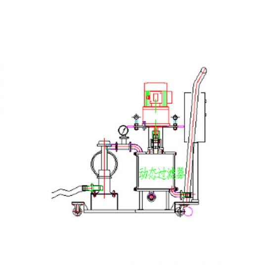
1. Slurry held in the transfer tank is pumped (via a diaphragm pump) through pipelines for filtration and iron removal, after which it is conveyed to the coating machine's hopper.
2. All components are connected using quick-connect fittings and mounted on a stainless steel tray; the transfer process is controlled by the control system and piping.
3. Note: Valves and level control devices between this system and the coating hopper/tank are to be installed and managed by the customer and coating machine supplier.
II. Equipment Configuration & Capacity
|
No. |
Name |
Spec. / Model |
Unit |
Qty |
Remarks |
|
1 |
Pneumatic Diaphragm Pump |
3/4" – Skylink or Graco |
set |
1 |
with ISO quick clamp |
|
2 |
Filter Cartridge |
Φ76 × 200 mm (100–250 mesh) |
pc |
1 |
– |
|
3 |
Magnetic Bars |
Φ25 × 156 mm, 10 000 GS |
pc |
3 |
– |
|
4 |
Pressure Gauge |
Φ60, 0–1 MPa, SUS304 |
pc |
1 |
– |
|
5 |
Scraper Assembly |
Triple‑blade, PTFE scrapers / SS springs |
set |
1 |
– |
|
6 |
Tubes & Valves |
Φ25, SUS304 |
set |
1 |
– |
|
7 |
Stainless Tray |
Custom size (L × W × H) |
pc |
1 |
SUS304 |
|
8 |
Control Box |
Level, pressure, alarm, control |
pc |
1 |
SUS304 |
|
9 |
Transfer Capacity |
20 L/min |
– |
– |
working flow |
III. Additional Notes & Precautions
1. Shaft seals, scrapers, and filter elements are consumables.
2. System is intended for single‑slurry, continuous production; frequent formulation change or batch interruption is discouraged.
3. When changing material system, clean lines & magnetic filter and replace key parts (filters), preferably new tubing.
4. Keep pipelines filled with slurry to avoid air/moisture ingress that may cause gelation.
5. Overall Dimensions: L 500 × W 1000 × H 900 mm






Wechat:17720812054 Whatsapp:+86 13174506016 Email:David@batterymaking.com

Wechat:17720812054 Whatsapp:+86 13174506016 Email:David@batterymaking.com

Wechat:17720812054 Whatsapp:+86 13174506016 Email:David@batterymaking.com

Wechat:17720812054 Whatsapp:+86 13174506016 Email:David@batterymaking.com

Wechat:17720812054 Whatsapp:+86 13174506016 Email:David@batterymaking.com

Wechat:17720812054 Whatsapp:+86 13174506016 Email:David@batterymaking.com

Wechat:17720812054 Whatsapp:+86 13174506016 Email:David@batterymaking.com

Wechat:17720812054 Whatsapp:+86 13174506016 Email:David@batterymaking.com

Please read on, stay posted, subscribe, and we welcome you to tell us what you think.


 IPv6 network supported


