Lab Helium Leak Testing Equipment Semi-Auto Helium Leak Detector Machine for Prismatic Cell Production
1、 Overview
This equipment is also suitable for dry leak detection of the finished battery cells of square prismatic cell (hereinafter referred to as workpieces) after liquid injection and sealing and nail welding. Manually loading and unloading the finished battery cell workpieces (sealing and nail welding) that have been filled with helium into a vacuum box, and then using the vacuum box method for helium mass spectrometry gas tightness testing, the device can determine whether the inspected workpieces are qualified or unqualified.
The system is designed and manufactured strictly in accordance with the requirements of the purchaser, adopting a modular design that fully considers the purchaser's leak detection requirements. At the same time, standardized modules and components are also used as much as possible to ensure the reliability and maintainability of the system, and meet the technical specifications specified by the manufacturer.
2、 Main technical parameters and requirements
|
Volume of inspected workpiece
|
≤ 2L
|
|
Maximum external dimensions of the workpiece
|
180mm X 50mm X 220mm (subject to the drawings provided by the demander)
|
|
Detection accuracy
|
approximately 5 × 10⁻⁷ Pa.m3/S
|
|
Leakage detector opening inspection (vacuum box) pressure
|
≤ 40pa
|
|
Leakage rate control setting
|
The demander sets it on the leak detector or system according to their own process requirements
|
|
Vacuum box inner chamber size and volume
|
L250 × W100× H300mm, approximately 10L
The size of the vacuum box shall be determined by both parties based on the existing maximum workpiece size. If Party A adjusts the workpiece size or placement method in the later stage, resulting in changes in the volume of Party B's vacuum box, a supplementary agreement shall be signed or the testing time of the vacuum box shall be extended according to the proportion of vacuum box increase.
|
|
Number of vacuum boxes
|
2
|
|
Number of pieces tested per box
|
2
|
|
Vacuum box opening and closing method
|
Drawer type
|
|
Vacuum box working rhythm
|
40S/box (including loading and unloading time less than 8.0S), 2 pieces per box, meeting 60S/time,
|
|
Working mode of vacuum box
|
Manual feeding, single loading of 2 cells
|
|
Method of entering and exiting the vacuum box for workpieces
|
manually grasping and transporting the workpieces into and out of the vacuum box
|
|
Automation control scope
|
1) The workpiece automatically flows into the inspection waiting station along with the assembly line. The workpiece is manually transported into and out of the vacuum box, and the start button is pressed. After the system detects that the workpiece is in place, it automatically works, recognizes, controls, and alarms according to the program, and processes them separately. The touch screen displays the working process or alarm;
2) The display device can display the working process, dynamic leakage rate, qualified and unqualified, fault diagnosis, and perform statistics;
3) Equipped with production statistics function: able to display the number of inspections, qualified, unqualified, and qualified rates per shift.
4) Operating parameters such as leakage rate, detection time, detection pressure, alarm value, etc. that do not affect equipment operation can be set according to process requirements (set through password on the touch screen);
5) The electrical control system has various reliable interlocking and protection functions. When the protection device is activated, it will stop completely and have an alarm prompt;
6) Fault statistics function, able to record the latest fault time;
7) The automatic helium cleaning function is intact, which can quickly and effectively eliminate residual helium gas inside the box and on the pipeline, with reliable leak detection accuracy and repeatability;
8) Modular design of various components within the system, reasonable layout, easy disassembly, replacement, and maintenance of vulnerable parts;
9) The device has password protection function to prevent unrelated personnel from modifying parameters or manual operation; And can set multiple parameter groups to facilitate parameter settings for products with different requirements;
10) The equipment should have a box calibration function, so that workers can calibrate the equipment on a daily basis;
11) The system reserves standard communication protocols for easy connection with subsequent operating platforms and conveying pipelines, enabling seamless connection between the helium detection part and the robotic arm and workpiece conveying, making overall control and system expansion more convenient.
|
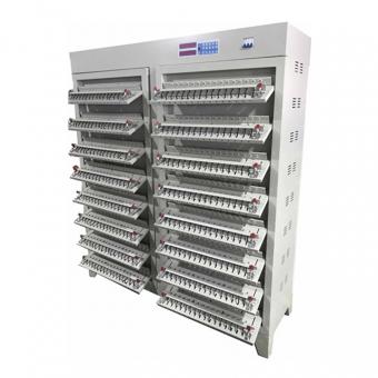
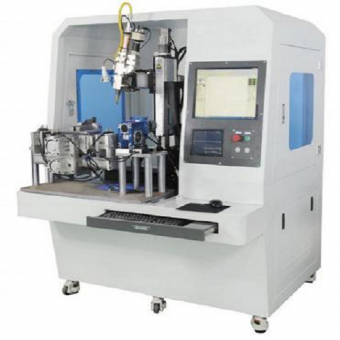
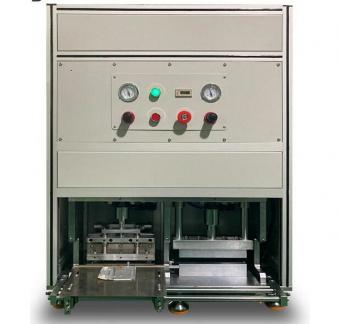
Figure 1: Similar effect diagram of the box (installation form of sealing nails for the inspected battery cells), specific design shall prevail
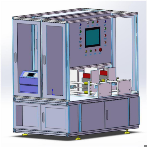
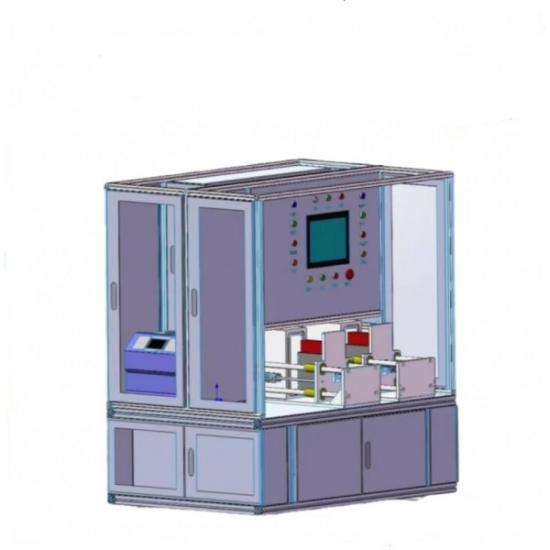
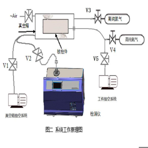
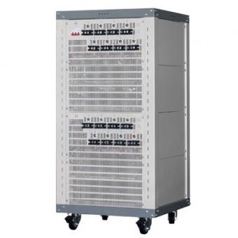
Figure 2 Schematic diagram of box layout, specific subject to design
3、 System Introduction
3.1 Vacuum box section
The vacuum box is composed of a vacuum box, a workpiece positioning device, a vacuum pump group, a vacuum measuring device, an electromagnetic valve, a pneumatic door opening device, a pipeline, and a frame.
The vacuum box is made of stainless steel or hard aluminum material, and its internal surface is polished and cleaned after processing, ensuring a good background and minimal gas accumulation, improving the pumping speed of the vacuum box. The vacuum box door adopts a pneumatic switch mechanism, which is simple and reliable to operate, greatly improving the leak detection efficiency.
The vacuum measurement device adopts the Pilani vacuum measurement of Infilcom, and the solenoid valve adopts the products of German GSR or Botti
3.2 Leak detector section
The leak detector mainly consists of a helium mass spectrometer leak detector, a control valve, and a calibration section. The helium mass spectrometer leak detector adopts A100 helium mass spectrometer leak detector with advanced technology, stable performance and convenient installation and maintenance.
3.3 Electrical control part
The electrical control part adopts PLC control, which organically combines the leak detector, vacuum box, and inflation discharge part, making the control system more coordinated, stable, and reliable. It also displays and sets various information on a color touch screen, such as evacuation time, vacuum box vacuum, alarm value, leakage rate, etc. The system can set different parameters based on the type of workpiece to be detected, and save these parameters in the system for selection when needed for production. The system can store parameters of various workpieces, and there should be corresponding prompts when setting each parameter.
Electrical control has the following functions:
*All parameters of the device can be displayed and modified on the touch screen, and have password protection function. The device parameter types are divided into user parameters and system parameters. Users can enter the corresponding level parameter setting system based on different permissions and passwords to perform parameter setting operations.
*When a system alarm occurs, it will automatically enter the alarm screen with an audible prompt. Press the alarm confirmation button to return to the initial operation interface.
*Each component (including vacuum pump, etc.) can be operated and debugged on the touch screen.
*It has a manual operation screen, and the process functions of manual operation are the same as those of automatic operation.
*There is a PLC status monitoring screen that can clearly display the operation status of various parts of the equipment, achieving real-time monitoring and control of system operation.
*It has the function of accumulating the number of unqualified boxes after each startup, and can be manually reset to zero.
*Equipped with fault diagnosis function.
*Equipped with self calibration, chain protection and alarm functions, as well as emergency stop buttons, ensuring the reliable and safe operation of the system itself and the safety of the inspected workpiece.
3.4 Introduction to Helium Cleaning System
The equipment has a helium cleaning function. When the leakage rate of unqualified products is too high, before the next leak detection, the system automatically fills the contaminated vacuum box and public pipeline with high-purity nitrogen to clear the helium background, ensuring that the equipment will not give false alarms due to helium background pollution in the vacuum box (i.e., high helium background) (the helium concentration in the surrounding environment cannot exceed the standard).
3.5 System Security Description
This system has the following security configurations to ensure the safety of system operation and operators:
1. Overload protection and overcurrent protection for vacuum pump unit;
2. Automatic protection for nitrogen overvoltage and undervoltage;
3. Helium overvoltage and undervoltage automatic protection;
4. Vacuum box door safety protection grating;
5. Automatic protection alarm for failure of vacuum pneumatic valve;
6. The leak detector is not ready for automatic protection alarm;
7. Automatic protection alarm in case of malfunction during the working process of the leak detector;
8. The leak detector automatically protects the alarm and waits when it is above the control point;
9. The vacuum box door has an in place signal to ensure no impact;
10. When there is a leak in the workpiece during leak detection and evacuation, an automatic alarm prompt will be given, and the distinction between qualified and unqualified workpieces will be clear;
11. Equipped with emergency stop switches on the operating surface and maintenance points, with corresponding safety operation instructions.
3.6 Equipment Appearance and Other Instructions
1. The layout of all components in the system is reasonable (display instruments, control switches, indicator lights, electrical components, filters, etc.), and all vulnerable parts are easy to disassemble, replace, and maintain;
2. Clear markings on both ends of the control line; The wiring base has corresponding terminal block text instructions;
3. Each gas pipe should be labeled with flow direction, and the wires should be equipped with wire grooves, with sturdy wire groove materials;
4. The pipeline routing is standardized and reasonable, with colors that comply with relevant national standards, and clear text and flow direction markings, without disorderly crossing.
5. Each air source and power supply should be equipped with a main switch and installed in an easy to operate position;
6. The leakage rate during leak detection can be displayed in front of the helium detector for easy viewing;
7. The motor direction of the equipment should be clearly marked, and protective devices such as protective covers should be added to the exposed transmission parts;
8. The instrument panel of the equipment complies with relevant industry standards and national standards;
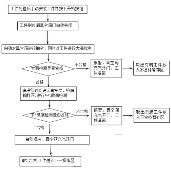
4、 System workflow
Workflow of Testing Finished Battery Sealing and nail welding System
Precautions:
When detecting the leakage of the sealing nail of the finished battery cell, the battery cell should not be lying on its side or upside down at this time to prevent the electrolyte from blocking the small leakage holes at the welding point of the sealing nail, which will affect the actual leak detection effect. The correct way is to place the battery cell cover plate facing upwards on the fixture.
5、 Working principle of vacuum box leak detection system
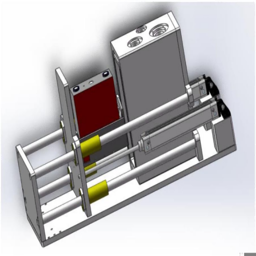
5.1 Introduction to Working Principle Diagram
5.2. Working principle of the sealing nail system for testing finished batteries
When the system is powered on and in standby mode, press the detection button, and the system will automatically switch to the finished battery cell sealing nail leakage detection mode. The steps are as follows:
1. Pressure test for major leakage
When detecting leaks, first place the finished battery cell workpiece that has been filled with helium in the previous process into the drawer of the vacuum box. The vacuum box door automatically closes and V1 valve is automatically opened to pre vacuum the vacuum box. At the same time, monitor the vacuum value of the vacuum box. If the true vacancy change in the vacuum box does not exceed the set value (such as 100 Pa) within the set time, it indicates that there is no major leak in the workpiece. Otherwise, it indicates that there is a major leak in the workpiece, and the system automatically gives an audible and visual alarm. Manually press the confirmation button to release gas and clear helium from the workpiece. The system ends the detection and prompts; If there are no major leaks on the workpiece, the system will continue to vacuum and check for minor leaks.
2. Check for minor leaks
If no major leakage is found, continue to evacuate the box for testing and simulate the working environment of the workpiece for medium to micro leakage testing. If the workpiece is not qualified, the system will give an alarm, otherwise the system will give a prompt. Inflate the vacuum box to open the lower part and enter the next detection cycle.
6、 Main configuration
|
|
Component Name
|
Origin/Model
|
quantity
|
|
helium mass spectrometer leak detector
|
Leak detector
|
Gebo Technology A100
|
1 set
|
|
Auxiliary pump
|
Leibao D16C
|
1 unit
|
|
Vacuum box part
|
Vacuum box
|
Stainless steel or hard aluminum
|
2 sets
|
|
Vacuum box opening device
|
SMC cylinder, etc
|
2 sets
|
|
Vacuum pipeline
|
Stainless steel
|
1 set
|
|
Vacuum valve
|
customization
|
1 set
|
|
Main pump
|
Laibao D60C
|
1 unit
|
|
Vacuum measurement
|
Yingfukang PSG500
|
2 pieces
|
|
Standard leak
|
Yingfukang TL4-6 (-5Pam/s~-7Pam '/s adjustable)
|
1 piece
|
|
Rack and fence
|
Armtech
|
1 set
|
|
Electrical control part
|
Programmable controller PLC
|
OMRON/SCHNEIDER
|
1 set
|
|
touch panel
|
WEINVIEW/OMRON/SCHNEIDER
|
1 set
|
|
Electrical components
|
SCHNEIDER, OMRON, etc
|
1 set
|
|
Electrical control cabinet
|
Armtech
|
1 set
|
7、 Spare parts list (vacuum pump adopts dry pump)
|
No
|
Name
|
Quantity
|
Noted
|
|
1
|
Vacuum pump oil
|
5L
|
|
|
2
|
Box sealing ring
|
2 pcs
|
|
|
3
|
Pipeline connection seal
|
1 set
|
|
8、 MES communication protocol description
1. Unification of data communication methods
Ethernet TCP/IP for data transmission
(1) The upper computer of the device requires data transmission to the industrial control computer (DCS, upper computer) or MES server through S7, MC, and FINS.
(2) The upper computer program of the industrial control computer and server calls the MES interface (Webservice, OPC), requiring the data to be collected to be transmitted to the MES database through Ethernet.
2. Provide secondary development services
All devices should have secondary development capabilities. The second party can carry out secondary development of PLC according to the needs of the first party, and the second party's software engineers and electrical engineering must unconditionally cooperate with the first party's MES implementation during the warranty period, and participate in the MES implementation work on site.
The second party shall provide the first party with the "Development Document" for free: PLC application layer program and annotations; The source code of the upper computer software application layer, encapsulated classes, and methods need to provide pre packaged code.
3. Each PLC shall reserve at least one 100 Gigabit Ethernet interface for MES use, which shall be transmitted to MES through TCP/IP requirements and support the addition of communication modules. The Ethernet interface cannot be converted through RS232RS485/USB data, it must be an integrated PLC Ethernet interface.


 en
en fr
fr de
de ru
ru es
es pt
pt ko
ko tr
tr pl
pl th
th


 IPv6 network supported